EDITOR: B. SOMANATHAN NAIR
1. INTRODUCTION
In the voltage-shunt feedback amplifier (VShFBA) configuration a voltage proportional to the output voltage is fed back in shunt with the input. A
practical implementation of this circuit is shown in Fig. 1. In the circuit
shown, a portion of the output voltage Vo is fed back in shunt with the input voltage Vbe through the feedback
resistor RF;
hence the name voltage-shunt feedback.

2. ANALYSIS 1: GAIN FACTOR OF VShFBA
For the voltage-shunt feedback circuit, as stated earlier,
we feedback a current If
(= BVo),
which is proportional to the output voltage Vo, in shunt with the input
voltage Vi.
Since BVo is
a current, we find that feedback factor B has the units of conductance (i.e.,
siemens) attached to it. The equivalent circuit of the voltage-shunt feedback
amplifier is shown in Fig. 2, and this will be used for the analysis.
It can be seen that the voltage-shunt feedback amplifier is a transresistance (current-to-voltage) amplifier, and
that we have to stabilize the transresistance (or, transfer resistance) with
voltage-shunt feedback.

Rmf = Vo/Is (1)
Referring to Fig. 2, we have from the input loop
Is = Ii + If = Ii
+ BVo (2)
where we have used the relation If = Ii
+ BVo. Similarly, from the
output loop, we find that output current
Io
= rmIi/(ro+
RL) (3)
Using the above equation, we find the output voltage as
Vo =IoRL
= rmIi RL/(ro+ RL)= RmIi (4)
where Rm =
rm/(ro+RL)
is the modified transresistance. Now, using the above equations, we get
Rmf = Vo/Is
= Vo/(Ii+BVo)
= Rm/(1+RmB) (5)
From Eq.
(5), we find that transresistance gets
stabilized with VShFB.
3. ANALYSIS 2: Input Impedance of VShFBA.
We define
input impedance with voltage-shunt feedback
as
Zif = Vs/Is (6)
Substituting
for, Is = Ii + If = Ii
+BVo and Vs = Vi, we get
Zif = Zi/(1+RmB) (7)
From Eq. (7), we find that input impedance decreases
with VShFB.
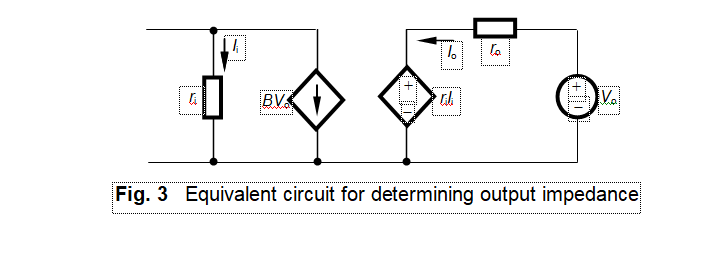
4. ANALYSIS 3: OUTPUT IMPEDANCE OF
VShFBA
To get the expression for the output impedance, we draw the
equivalent circuit, shown in Fig.3, based on the same principles stated
earlier, viz.,
·
Remove
the input current source by open circuiting the input terminals, leaving
the internal impedance of the source untouched.
·
Leave
all dependent sources and circulating currents untouched.
·
Remove
the load resistance from the output side, since the output impedance is defined
with this condition imposed on it.
·
Apply
an external voltage source across the output terminals and find the output
current due to this. As stated in the previous case, the direction of output
current Io
has become reversed (i.e., anticlockwise) in this process. This change in
the direction of Io
will produce a change in the direction of any source dependent on it. In this
case, such an action does not happen since the dependent source is BVo.
Zof
=Vo/o (8)
Io = (Vo ‒ rmIi)/ro (9)
From the input loop, we get
BVo = ‒/I (10)
Substituting for Ii from Eq. (10) into Eq. (9), we have
Io
= (Vo + rm BVo)/ro (11)
Rearranging Eq. (11), we get
Zof = ro/(1+rmB) (12)
From Eq. (12), we obtain that output impedance decreases
with VShFB.
Note: It is interesting
to note that the inverting configuration
of opamp is a voltage-shunt operation and the non-inverting configuration is a voltage-series operation.


No comments:
Post a Comment