EDITOR: B. SOMANATHAN NAIR
1. INTRODUCTION
In the current-shunt feedback
amplifier (CShFBA), current proportional to the output current
is feedback in shunt
with the input. A practical
implementation of this configuration is shown in Fig. 1. In the circuit shown,
we notice that output (collector) current Io flowing through emitter resistor RE develops a voltage IoRE across it, which is
fed back in shunt with the input voltage Vbe through the feedback resistor RF; hence the name current-shunt
feedback.

2. ANALYSIS 1: GAIN FACTOR
OF THE CShFBA
In the current-shunt feedback
circuit, as stated earlier, we feed back a voltage Vf (= BIo = IoRE), which is
proportional to the fed-back current If, in
shunt with the input voltage Vi. Since BIo is a current, we find that feedback factor B is a
mere number and has no units attached to it. The equivalent circuit of the
current-shunt feedback amplifier is shown in Fig. 2 and this will be used for
the analysis.

·
Output
section is the Norton equivalent circuit of the hybrid model, with the
following equivalences:
aiIi = hfeIb
ro = 1/hoe
·
Input
section is converted into a Norton equivalent circuit, with
BIo = -hreVori
ri = hie
·
We
find that current-shunt feedback amplifier is a current (current-to-current)
amplifier and that we have to prove that current
gain Aif gets stabilized in this case. We define current gain Aif as
Aif = Io/Is (1)
Referring to Fig. 2, we have from the input loop
Is = Ii
+ If = Ii + BIo (2)
where we have used the relation If = BIo.
Similarly, from the output loop, we find that output current
Io = aiIiro/(ro + RL) = Ai Ii (3)
where we define a modified current gain Ai as
airo/(ro + RL) = Ai (4)
Now, using the above equations, we get
Aif = Ai/(1+ AiB) (5)
From Eq. (5), we find that current gain is stabilized with CShFB.
3. ANALYSIS 2: INPUT
IMPEDANCE OF CShFBA
We define input impedance with current-shunt feedback as
Zif
= Vs/Is (6)
Substituting for Vs = Vi, and Is = BIo + Ii,
we get
Zif = Vi/(Ii + BIo) = Vi/(Ii + BAiIi)
= Zi/(1 + AiB) (7)
Inspection of Eq. (7) reveals that input
impedance decreases with CShFB.
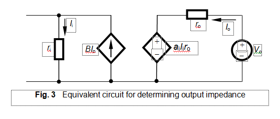
4. ANALYSIS 3: OUTPUT IMPEDANCE OF CSHFBA
To get the expression for the output
impedance, we draw the equivalent circuit, shown in Fig. 3 based on the same
principles stated earlier, viz.,
· Remove
the input current source by open circuiting the input terminals, leaving
the internal impedance of the source untouched.
·
Leave
all dependent sources and circulating currents untouched.
· Remove
the load resistance from the output side, since the output impedance is defined
with this condition imposed on it.
·
Apply
an external voltage across the output terminals and find the output current due
to this. As stated in the previous case, the direction of output current Io has become reversed
(i.e., anticlockwise) in this process. This change in the direction of Io will produce a change in the
direction of any source dependent on it. In this case, such an action occurs.
We find that we have to reverse the direction of the dependent source BIo, when direction of Io is reversed. This is shown in
Fig. 3.
As before, we define output impedance with feedback as
Zof
= Vo/Io (8)
From the output loop (converted into an equivalent Thevenin),
using KVL, we find
Io = (Vo ‒aiIiro)/ro (9)
From the input loop, as the direction of Io has been reversed, we
get
BIo = Ii (10)
Substituting for Ii from Eq. (10) into Eq. (9), we have
Io = (Vo ‒ai BIoro)/ro
(11)
Rearranging Eq. (11), we get
Zof
= ro (1+aiB)
Equation (11) reveals that output impedance increases
with CShFB.


No comments:
Post a Comment