Sunday, 15 April 2018

AMPLIFICATION

B. SOMANATHAN NAIR
     
      When we hear the word amplification, we get the feeling that a small quantity of an item is made into a much larger quantity of that item by using a specially made instrument called amplifier. For example, an audio amplifier amplifies low-volume sound signals into a high-volume sound signal. But, there is one problem for this definition: it is against the law of conservation of energy. According to this law, a small quantity of energy can not be converted into a large quantity of energy; one form of energy can be converted into another form only without any change in its magnitude. Then what is amplification?

AMPLIFICATION (IDEAL DEFINITION)

Amplification is the process of controlling the flow of energy, the controlling energy being negligibly smaller than the controlled energy.

ILLUSTRATIVE EXAMPLE 1

The ideal definition says that amplification is the control of flow of energy. In this ideal definition, we do not find any word that has any relation to the word amplification. Then how can we say that this is the definition of amplification?   
            Let us consider a procession in which there is one leader and five followers as shown in Fig. 1. The leader shouts a slogan and his followers repeat the same in the same way the leader has shouted. The combined voice of the five followers gives an amplified version of the leader’s voice by a factor of five. In other words, we say that in this operation, we get amplification by a factor of five.

 The following points are important in this context:

1.       There is one input voice.

2.       There are five output voices.

3.     The input voice is able to control the output voices. For example, if the input says, “Jai Sriram”, all the outputs will say, “Jai Sriram”. Now, if the input says, “Jai, Jai, Jai Sriram”, the outputs will also say, “Jai, Jai, Jai Sriram”. Thus the outputs follow the variations in the input exactly in the same fashion, but at a much larger volume. Hence, we say that the system consisting of one leader and five followers has produced an amplification of five.

4.  In this case, the law of conservation of energy is not violated, i.e., we are not generating a large energy from a small energy. Both small (i.e., leader) and large (five followers) energies exist; only, the small energy is controlling the large energy in such a way that the variations in the small (controlling) energy are reproduced exactly in the same fashion in the large (controlled) energy. Incidentally, we find that this is the ideal definition of amplification (i.e., small energy controlling large energy).

5.    It may be noted that the controlling and controlled energies are both DC energies (i.e., there are no variations in them).

6.     We super impose the signal to be amplified to the controlling energy and apply it to the input section of the amplifying device.

7.   The amplifying device then produces variations in the larger energy in its output section corresponding to the variations in the input energy. The larger output, which reproduces the input variations exactly as such, then gives amplification.


ILLUSTRATIVE EXAMPLE 2      


Consider a laser torch emitting 1 milliwatt of red laser light (Fig. 2). Let this light be used for communication between a man on ship and a man on the shore. First assume that the shoreman sends laser light to the shipman. A steady laser light is a DC signal and has no meaning. To send information, we must use variations in the DC light, which are known as codes.
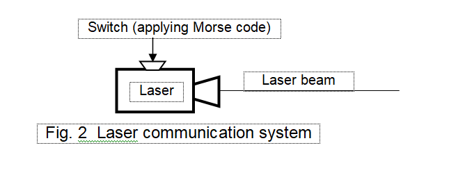
        There several coding schemes that we use. In this case, let us assume that Morse code is used, which makes use 1s and 0s for information transmission. 1s may be represented by presence of a short light pulse while its absence may be used to represent 0 (or vice versa). The laser light can be switched on or off by a small switch on the outer cover of the laser; a slight pressure on the switch will turn on or off the laser light.
Now suppose the shoreman wants to send certain information to the ship. He will prepare the Morse code of the information first and then press the laser switch as per the codes formed. The pressing of the laser key requires negligible power. Thus the power input is very small and this creates the signal input energy. But this input energy creates corresponding variations in the large laser energy so that the shipman can read the message by decoding the variations in the light energy. In this case, we see that amplification has occurred, since the input energy (pressing of the laser switch) is small, but the output energy (laser light) is large.          

ILLUSTRATIVE EXAMPLE 3


Consider now a common-emitter electronic amplifier. In this case, input current is the base current (microampere range) and output current is the collector current (milliampere range). Since 1 mA is 1000 μA, amplification is possible in this case. This is because the small variations in the base current can create corresponding variations on a lager scale in the collector current (for further explanation on CE amplification, see the forthcoming blog on CE amplification).


Friday, 6 April 2018

WHY DO WE NEED DIRECT CURRENT IN COMMUNICATION?


B. SOMANATHAN NAIR

We require multiple-level current or voltages for signal representation. The minimum number of levels that we require for this purpose is two and we call this as the binary system. Direct current has only one level and hence it cannot be used to represent signals. But we find that DC currents and voltages find extensive application in electronics and communications. For example, most of the electronic devices require DC voltages for their operation.
            A course in electronic circuit theory usually starts with the theory of half-wave and full-wave rectifiers. But usually no descriptions are seen about the importance of DC current and rectifiers in the electronic circuit textbooks that a student generally follows. The following illustrative examples will highlight the importance of DC in communication.

ILLUSTRATIVE EXAMPLE 1

Consider the case of human conversation. Let one man talk to another man. Here the preposition to shows the direction of flow of human voice energy. Once the direction of energy flow is fixed, then we no longer use the word to show the direction of signal flow. It can also be seen that to represents one direction and hence constitutes a DC signal, which means that in a conversation, DC is used to indicate direction. Without this unidirectional energy flow we can not communicate with each other. But once we get the direction of sound energy flow, we no longer care for this DC component.

ILLUSTRATIVE EXAMPLE 2

Let us now take the case of human vision. Consider a room in which some objects are kept. We see these objects when a steady (DC) light (such as a tube light) is present. Here the light acts as the DC part and the objects act as signals. Once we start to see objects we no longer are bothered about the DC light source. However, we are bothered about the light source when it becomes off and we can not see the objects even though they are still there in the room.  Thus DC light acts as the background which help us to see objects. It may be noted that it is difficult to see objects when the steady DC light is replaced with a variable light source, whose intensity varies at every instant.  

ILLUSTRATIVE EXAMPLE 3

Consider a white board (or computer screen) for writing. A white board may be considered as a DC surface, because it carries a steady whiteness on its surface. Now let us write something on the surface. The white background now carries signal on it. Without the background surface, we can not write anything on it. Thus DC acts as the background in this case. Once the idea is written on the board, we no longer care for the background board unless it becomes too shady that we can not write anything further on it.  

ILLUSTRATIVE EXAMPLE 4

Consider the traffic through road, rail, sea etc. suppose we concentrate on road traffic using a car. Car takes a person from one destination to another. Since this is a directional movement, we can say that the car is a DC source. The person is the signal. The car (DC) carries the signal (person) from one destination to another. Once this transportation is over, we no longer need the car and neglect this DC component.

ILLUSTRATIVE EXAMPLE 5

Consider now a common-emitter amplifier. In this amplifier, we forward bias the base-emitter region with about 0.65 volt DC, and reverse bias (indirectly) the collector-emitter region with 10 volt DC. These DC voltages are required to make the base and collector currents, respectively. Now, the signal to be amplified is superimposed above the input base current. Thus the base current is a variable DC (DC bias current + ac signal current). This variable DC current produces corresponding variable and amplified DC collector current. However, once we get the amplified collector signal current, we remove the DC component part in it by using a coupling capacitor and get the amplified signal current across the collector-emitter output terminals. It can be seen that the DC currents are used in this case also to give specific directions to the flow of collector and base currents. Once this is established, we discard the DC.

CONCLUSION

We have seen that DC is essential in every communication system. It shows direction of energy flow or background needed to support the signal. Without DC there is no communication. This is the reason why it is included in the electronic circuit theory syllabus.

Tuesday, 3 April 2018

HOW MUCH SECRECY IS THERE IN OUR ONLINE DATA TRANSMISSION?

B. SOMANATHAN NAIR

Currently, in India, a lot of discussions are going on regarding the safety of digital data transmitted through internet. Let us analyze the situation and see how safe our digital data are from intruders.
Suppose we sent an email to a friend. This involves the following operations. First we prepare the letter by typing it on our personal computer. Next we turn on our internet connection and access our email by using our email ID and password. After these operations, we access the email of the friend to whom the letter must be sent, and send the letter either directly or as an attachment. It can be seen that this is a simple procedure.
As stated above, sending and receiving emails is a simple procedure. We feel that because of the password protection, nobody else, except the sending and receiving parties of the email, can read the data sent over internet. This would have been true if the data were sent by enclosing it in a sealed cover. However, there is no cover in email transactions and hence there is no secrecy of data.
It is well known that all mail transactions are controlled by server computers, which are owned by the mail company. The data we sent over mail will be first stored in these server memories, from where they will be transferred to the recipient of the mail. These operations show that all the data transferred through email are stored in the server memories of the email company and hence are not secret. The email company can access these data anytime they want.
Elaborating the discussions given above, we find that any data sent over internet are stored in the memories of the internet providing company and hence are not secret documents. This means that all online transactions are done with the knowledge of the internet provider; he will have access to all types of information that are transmitted through online. This point suggests that there are no data on internet that are private and hence secret.
The above point stresses one thing: Any data stored on the internet server memories can be read and viewed by the internet provider without any difficulty. However, it may be noted that these data can be viewed by hackers also. Hackers are people who illegally intrude into networks to steal data that are stored there. Password-security is not a problem for such people. There are several expert software engineers all over the world who work as expert hackers. No security measures are a problem for such people. They are expert crackers who steal into various networks and access data stored therein.
            Now, consider the claims that data stored in personal identification cards of a person are safe by various authorities of government. From the arguments given above, we can see that these claims are thoroughly false. It is clear that all the information regarding a person stored in his personal identification card is known to the internet service provider and hacking experts. Hence, it is astonishing to know that some service providers are summoned by various governments to explain the leakage of personal data.
            In this context, it is surprising to note that some educational organizations send question papers and answer papers online to agencies who conduct the examinations. It is not surprising to hear that the question papers have leaked.
            Similarly, in election polls using voting machines, manipulations are possible. Expert hackers in IT field can manipulate the results of the election.
            It is further interesting to note that nothing is a secret now-a-days in this world. We believe that what we are doing inside the four walls of our room is totally invisible to any outside person. This idea is also wrong. There are several satellites sent by various governments and agencies orbiting around the earth. Some of these satellites are designed as spy satellites, which can snoop into the private life of persons. These satellites carry very powerful cameras working on infrared frequencies. They are so sensitive that they can snoop into the rooms of houses and take the images of activities taking place in these rooms. Since the frequency involved is infrared, the affected parties will have no knowledge about the photoshoot from the satellite. This idea is alarming; however it is a reality now. Thus the phrase ‘privacy of persons’ no longer exists. This means that we have no privacy in our life. Governments and corporates decide our fate.

Saturday, 9 December 2017

A SIMPLE NON-MATHEMATICAL PROOF OF LENZ’S LAW

Editor: B. Somanathan Nair


ABSTRACT: In 1831, Michael Faraday enunciated the law of electromagnetic induction. This law states that whenever a conductor cuts a magnetic field, an electromotive force (EMF) is induced in it. In 1835, Heinrich Lenz enunciated the Lenz's law, which states that when an EMF is generated by a change in magnetic flux as per Faraday's Law, the polarity of the induced EMF (or, voltage) is such that it produces a current whose magnetic field opposes the change which has produced it. This law also has been accepted (just like the Faraday’ law) by the scientific world as such without any modification for nearly two centuries now. The proof of this law is usually given on the basis of the Law of Conservation of Energy, which involves complex mathematical explanations. This paper gives a very simple, naturally logical, and non-mathematical proof of the Lenz’s law. In this connection, it may be noted that this paper is an extension of our previous blog on Faraday’s law..


1.    INTRODUCTION

       Lenz’s law has been regarded as similar to Newton’s third law of motion, which states that for every action there is an equal and opposite reaction. Considering this law, we find that, if a current produces a magnetic field, it is natural to assume that this action has a reaction by which the generated magnetic field produces a reverse current which then naturally is opposite to the first current. The proofs given so far have been based on this concept and scientists used the Law of Conservation of Energy to prove the Lenz’s law. In one of the articles on Lenz’s law, the concepts of pressurized aether and electron-positron dipole are used for proving the Lenz’s law1. We now state that Lenz’s law is not at all that complicated and can be proved non-mathematically by using simple and natural logic.

2. MAGNETIC INDUCTION2

      Consider an experiment in which a straight copper conductor AB being applied with an ac voltage across its terminals, as shown in Fig. 1. A straight-conductor concept is used here for simplifying the explanation.

      During positive half-cycles (PHCs) of the input ac voltage, when the top terminal A of the conductor is positive with respect to its bottom terminal B, free electrons in the conductor move upwards through it towards A and an electron current I1e flows through the primary conductor from B to A. This is indicated by green-coloured dotted-line block arrow in Fig. 1. The conventional current I1p, corresponding to I1e, indicated by the orange-coloured block arrow in Fig. 1, flows in a direction opposite to that of I1e.

     Now, since electrons are also tiny magnets (dual property of electrons), as they move upwards, the magnetic field (indicated by blue-coloured circular dotted-line thin arrows) associated with them will also move upwards. It may also be noted that this magnetic field is oriented in a direction perpendicular to that of the electron flow. This is illustrated in Fig. 1. It may further be noted that since the applied ac voltage is sinusoidal, the current and hence the magnetic field generated are also sinusoidal.

      Let us now assume that a second conductor CD (with terminals and D being shorted through a suitable load resistance RL) be placed inside the same magnetic field, as shown in Fig. 1. It can be easily observed that in this case, the magnetic field produced by I1e in the first conductor AB in turn interacts with the free electrons in the second conductor CD and deflects them so that they move in a downward direction through itThis reversal of current flow is quite natural because it is the upward motion of electrons in AB that produced the magnetic field; this field in turn produces the motion of electrons in CD. Since this is a reverse process, naturally the direction of current flow in CD must be opposite to that in AB. The reversed electron current I2e and corresponding conventional current (I2p) are indicated in Fig. 1 using the cyan-coloured and blue-coloured block arrows, respectively.


     From the discussions given above, it has now been proved that a current will be induced in any secondary coil placed inside the magnetic field generated by a primary current. This principle may be extended in the form of a general statement:

Current will be induced in all the secondary conductors placed inside the magnetic field generated by the current flowing through a primary conductor. This is true for all the conductors located near or far away from the primary provided that the effect of the magnetic field generated by it is sensed at these locations.

     The general statement given above is illustrated in Fig. 2. In this figure, P is the primary conductor, which carries conventional primary current I1 (represented by the longest orange-coloured block arrow). There are n secondary conductors S1 to Sn, located at different distances inside the same magnetic field produced by I1. The induced secondary conventional currents I21 to I2n are indicated by green-coloured block arrows drawn on each secondary conductor. The lengths of these arrows are shown as decreasing with increasing distance from P. This indicates that the magnitude of the current induced in a secondary conductor decreases as the distance between that conductor and P increases. The directions of the currents shown in Fig. 2 are for positive half-cycles of the input voltage (for negative half-cycles, these directions reverse). 


     Since the statement given above is true, it also suggests that there will be a current induced in the primary conductor itself, considering it as a secondary conductor placed inside the same magnetic field generated by the primary current. Since we are now considering the primary conductor as a secondary conductor, the current I2 induced in it by the magnetic field due to primary current I1 will be in a direction opposite to that of I1. These actions are illustrated in Fig. 3. Here, I2 is produced as a self-induced current and hence this process is called self-induction.

       The actions explained above is in effect is the statement of the Lenz’s law. It can be seen that this effect is produced because the same coil can act as the primary and secondary coils. Thus the proof of the Lenz’s law is very simple and straightforward; it does not require the support of the Law of Conservation of Energy (which is currently used for its proof) to prove it.


3.    SELF-INDUCTANCE REDEFINED

Lenz’s law suggests that an ac current is generated within a conductor when an externally applied ac voltage drives an ac current through it; the direction of flow of this induced current is opposite to that which has generated it. This in effect suggests that the new induced current opposes the very current that has generated it. This gives rise to what is known as self-inductance.

Note: In this article, we have frequently used the term ac current for alternating current. Even though, in reality ac means alternating currentwe have used it here just to mean it as alternating or varying. This is in conformity with usages such as ac voltageac magnetic field, and ac light.


4.    SUMMARY

We have presented through this article a very simple and logical proof of the Lenz’s law. This has the following features:

      1. There is no mathematics involved in this proof.

      2. It does not make use of the Law of Conservation of Energy.

      3. It also does not use any aether concept.

      4. It does not make use of the electron-positron dipole concept.

5. It makes use of the Faraday’s law of magnetic induction in its modified form, which states that the primary itself can be regarded as a secondary.

5.    ACKNOWLEDGEMENT


We state that the figures shown in this article are drawn using the DRAWING TOOLS available in the Microsoft word software. It may be noted that these tools are extremely useful to prepare drawings in two and three dimensions. In all our articles, we shall be using these tools. We acknowledge our gratitude to the Microsoft Corporation for creating this excellent software package.

  
6. REFERENCES

1. Frederick David Tombe: “Lenz’s Law”, The General Science Journal, 2009.

2. B. Somanathan Nair, P. S. Chandramohan Nair, S. R. Deepa, N. Anand: "Some New Perceptions on the Magnetic Field and the Radiating Properties of Antennae", IEEE International Workshop on Optical Networking Technologies and Data Security (ONTDS), 2014.


Friday, 8 December 2017

A RE-LOOK INTO FARADAY’S LAW OF ELECTROMAGNETIC INDUCTION BASED ON ELECTRON THEORY

EDITOR: B. SOMANATHAN NAIR


ABSTRACT: Michael Faraday enunciated the law of electromagnetic induction in 1831. This law states that whenever a conductor cuts a magnetic field, an electromotive force (EMF) is induced in it. This law has been accepted by the scientific world as such without any modification for nearly two centuries now. In this paper, we investigate the completeness of the statement of Faraday’s law and suggest some modifications in its statement so that it explains the action of what is known as (electro) magnetic induction. 

1.    INTRODUCTION

Faraday’s law of electromagnetic induction (or simply, magnetic induction1) states that whenever a conductor cuts a magnetic field, an electromotive force (EMF) is induced in it. Everybody in the scientific world has accepted this law as such without any question being asked about its completeness. There is no doubt about the truthfulness and validity of this law. However, a couple of questions arise in this case which nobody has raised or answered so far:

      1. What is electromagnetic induction?
      2. What is the speed with which induction takes place in a conductor?

In this paper, we attempt to give answers to these important basic questions and suggest some more aspects that may be included in the Faraday’s law.

2. EXPERIMENTAL DEMONSTRATION OF THE PROCESS KNOWN AS ELECTROMAGNETIC INDUCTION

      Consider an experiment in which an ac voltage (or, EMF) is applied across the terminals of a straight metallic (say, copper) conductor AB as shown in Fig. 1. A straight-wire conductor is used here for the simplification of explanation.
    During positive half-cycles (PHCs) of the input voltage, when the top terminal A of the conductor is positive with respect to its bottom terminal B, free electrons in the conductor move upwards from B to A, which results in a primary electron current I1e flowing from B to A. This is illustrated in Fig. 1 by the green-colored dotted-line block arrow shown as superimposed over conductor AB. In Fig. 1, we have also shown the conventional primary current I1p corresponding to I1e, indicated by the orange-colored block arrow. It must be remembered that the direction of electron current (due to the flow of negative charges) and that of the conventional current (due to the flow of positive charges) corresponding to this electron current are mutually opposite to each other. This is the reason why the green-colored and orange-colored block arrows are shown in opposite directions.
      Now, since electrons are also tiny magnets (their natural dual property), as they move upwards, the magnetic field associated with them (indicated by the blue-colored dotted-line circular arrows) will also move upwards. It may be noted that this magnetic field is oriented in a direction perpendicular to that of the electron flow, as illustrated in Fig. 1. It may also be noted that since the applied ac voltage is sinusoidal, the resultant primary current and the generated primary magnetic field are sinusoidal with their respective frequencies the same as that of the input voltage. This means that, if the input voltage is of 50 Hz, then the generated alternating current and ac magnetic field are also of 50 Hz.

     Let us now assume that a second copper conductor CD (with terminals C and D being connected through a suitable load resistance RL) be placed inside the same magnetic field, as shown in Fig. 1. It can be easily observed that in this case, the magnetic field produced by the electron current flow I1e in the primary conductor AB in turn interacts with the free electrons in the secondary conductor CD and deflects them so that they move in a downward direction through it (i.e., CD). This reversal of current flow is quite natural because it is the upward motion of electrons in AB that produced the magnetic field; this field in turn produces the motion of electrons in CD. Since this is a reverse process of the first action, naturally the direction of the current flow in CD must be opposite to that in AB. The reversed secondary electron current I2e and the conventional current (I2p) corresponding to it are indicated in Fig. 1 using the cyan-coloured and the blue-coloured block arrows, respectively. It may further be noted that both I2e and I2p possess the same frequency as that of I1e.


It can also be seen that the generated primary magnetic field is an alternating quantity, it spreads around the primary conductor with the same frequency as that of the primary current and at a velocity equal to that of the light. In this connection, we remember that the magnetic force generated by a magnet can be felt at places far away from its original location (natural property of a magnet); the more powerful the magnet, the more the distance at which its effect is felt. Also, if this magnetic field is alternating with a frequency of f Hz, then its effect will be felt at a distance of 3×10⁸ meters at the same frequency of f Hz after 1 second. This means that current is generated (or, induced) in the secondary coil with a frequency of f Hz and at a speed equal to that of the light. It may further be noted that it is the magnetic field (in the form of waves) that is spreading through space; there is no electric-field component attached to this. Actually, electric part of these magnetic waves occurs only when they are intercepted (or cut) by a conductor and then they induce a current in it. Thus the term electromagnetic wave is a misnomer. It must be actually redesignated as magnetic wave and not as electromagnetic wave.1

From the discussions given above, we observe that when a conductor is placed inside a varying magnetic field, a varying current of the same frequency is produced in it due to the deflection of free electrons in it by that magnetic field. This clearly suggests that it is an alternating current, and not an EMF, that is generated in a conductor when it is placed in an alternating magnetic field. The EMF mentioned in the Faraday’s law can be seen to be the potential drop that is produced in the conductor due to this current flow. However, due to long-term usage, the term magnetic induction can be used to indicate the generation of an electromotive force (voltage) also.

Figure 2 shows the situation during negative half-cycles (NHCs) of the applied ac voltage. During the negative half-cycles, terminal B becomes positive with respect to terminal A and hence electrons in the conductor move downwards reversing the direction of current I1e through AB. In this condition, we notice that the associated magnetic field has also reversed. This in turn results in an upward motion of electrons through conductor CD. Thus we find that current I2e also gets reversed in this case, as shown in Fig. 2. 


3.    STATE OF AFFAIRS WHEN THE SECONDARY IS OPEN

In Section 2, we had assumed that the secondary is shorted through a load resistance. A pertinent question arises here: What will happen if the secondary terminals are kept open? In fact, original Faraday’s law states that a voltage is induced in the secondary when a magnetic field is cut by that conductor. This statement suggests that the secondary is open.
According to Section 2, to have a current flowing through it, the secondary must form a closed path; then only electrons in that coil can move to produce the current. However, how can a current flow through a conductor if it is open?
  The problem given above can be solved by considering the fact that there always exists a very low-value parasitic capacitance with air as dielectric across the terminals of a conductor carrying currents of opposite polarity (a basic property of a capacitance). Based on this property, we find that there always exists a parasitic capacitance CP across secondary terminals C and D as shown in Fig. 3. It can be easily seen that it is this capacitance CP that completes the required secondary path through which the secondary current is flowing. This current in turn develops a voltage drop across CD, which forms the open-circuit secondary voltage (as per Faraday’s law).


A similar action as given above takes place during the negative half-cycles. The only difference is that, as illustrated earlier, the directions of currents reverse in this case from those shown in Fig. 3. However, no figure is given for this case, since it is similar to Fig. 2, with Rreplaced with CP.
It is found that CP will be usually in the range of a few picofarads so that the secondary current will be usually very small (maybe on the order of a few picoamperes). The following calculations will prove this fact.
Let the secondary voltage be equal to 10 volts and let CP be equal to 10 pF. Then, for a 50-Hz ac, the capacitive reactance XCP = 1/2πfC = 318.3×10ohms. The secondary current, therefore, will be 10/318.3×106 = 31 nanoamperes (approximately). This current is usually considered as negligible. However, it may be noted that if the input frequency is raised to 1 GHz, the secondary current will be about 0.6 ampere, which is a large value compared to 31 nA.

4.    SUGGESTED NEW ADDITIONS TO BE INCORPORATED INTO THE EXPLANATION OF ORIGINAL FARADAY’S LAW

      We now suggest that the following points may be incorporated into the explanation of original Faraday’s law so that it may become more clarified.

      Whenever a conductor cuts a magnetic field, free electrons in it get deflected by the field producing a current flow through it. This current will be a transient direct-current spike if the magnetic field is a DC field; it will be an alternating current if the field is an ac magnetic field and continuous if the field is continuous. This current completes its path through the parasitic capacitance existing across the terminals of the conductor and develops a potential (or EMF) across its terminals. 

      As an alternative to the above, we may state: An ac current flowing through a conductor produces an ac magnetic field which spreads in the space surrounding it with a velocity equal to that of the light and deflects the free electrons in another conductor placed inside the same magnetic field; this produces an ac motion of the electrons resulting in an ac current being driven through it in a direction opposite to that in the first conductor; this ac current in turn produces an ac voltage drop across the terminals of the second conductor, which becomes the induced EMF in it.


The statements given above can be elaborated into the following actions, which may be used in explaining the Faraday’s law.


1. A DC magnetic field will produce a dc current spike or transient in conductor that cuts it.
2.  If the magnetic field is alternating and continuous, the generated current will also be alternating and continuous.
3.  In both the cases mentioned above, the current will flow through a path completed by the parasitic capacitance existing across the terminals of the conductor; producing a voltage drop (or EMF) in it.
4. Alternatively, if the magnetic field is generated by applying an ac voltage across a conductor (called the primary conductor), then free electrons in it gets deflected by the generated field producing an alternating motion of the electrons. This produces an ac current that flows through the primary conductor.
5. Since electrons are also tiny magnets (dual property), when they move through a conductor, they produce a moving ac magnetic field surrounding it in a direction perpendicular to the axis of the conductor.
6. The generated ac magnetic field spreads through the space surrounding the primary conductor with a velocity equal to that of the light.
7. Since this magnetic field is alternating in nature, it will interact with the electrons in a second conductor (called the secondary conductor) placed inside the same field and deflect them magnetically.
8. The deflection of electrons in the secondary conductor in turn produces an alternating current in it, when the secondary is closed through a connected load.
9. The direction of this secondary current can be seen to be opposite to that of the primary current. This is because the spreading magnetic field is produced by the primary current; this magnetic field in turn produces the secondary current. Since these two actions are mutually opposite to each other, direction of the current flow in the secondary has to be (and will be) naturally opposite to that of the current flow in the primary.
10. If the secondary is open (instead of a closed one, as proposed in the original Faraday’s law), then the secondary can be assumed to form a closed path through the invisible parasitic air capacitance of very low value that will always exist across the open-circuited secondary terminals. The secondary ac current (of very low value) will then flow through this completed path and produce a voltage drop across the secondary terminals, which will then act as the open-circuit secondary voltage (since the parasitic capacitance is invisible).
11. From the above arguments, it is also clear that current will be generated in all the conductors placed inside the same magnetic field.
12. In actual practice, straight conductors are replaced with multi-turn coils.


5.    SUMMARY

Through this article, we have introduced a few links that we feel are missing in the original Faraday’s law. In particular, we have:

1.  Given some more explanation required to define the process known as electromagnetic induction.

2.   Specified the speed with which induction takes place in a second conductor.

3. Explained on how the direction of the induced secondary current gets reversed with respect to the direction of its generating current.

4.   Given an explanation on how magnetic induction produces a voltage across an open-circuited secondary.

5.   Mentioned the fact that current gets induced in all the conductors placed inside the same primary magnetic field.


6.    ACKNOWLEDGEMENTS

It is specially mentioned here with thanks that the figures shown in this article are drawn using the DRAWING TOOLS available in the Microsoft word software. It may be noted that these tools are extremely useful to prepare drawings in two and three dimensions. In all our articles, we shall be using these tools. We acknowledge our gratitude to the Microsoft Corporation for creating this excellent software package.


7. REFERENCE

1. B. Somanathan Nair, P. S. Chandramohan Nair, S. R. Deepa, N. Anand: "Some New Perceptions on the Magnetic Field and the Radiating Properties of Antennae", IEEE International Workshop on Optical Networking Technologies and Data Security (ONTDS), 2014.


DISCRETE SIGNAL OPERATIONS

EDITOR: B. SOMANATHAN NAIR 1. INTRODUCTION In the previous two blogs, we had discussed operations of scaling and shifting on conti...